")
")
")
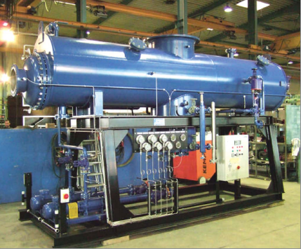
Water-cooled vacuum condensation plant
- Category: Condensers
We offer complete condenser installations including all necessary aggregates, such as vacuum systems, condensate pumps, condensate level control, safety valves etc.
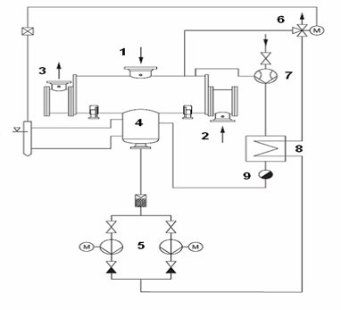
Water cooled vacuum condensation plant flow diagram
Operating principle
This condenser is a shell-and-tube type heat exchanger. Steam leaving the turbine flows to condenser pipe 1, passes around cooling pipes, condenses and get into a hot-well 4.
From a hot-well condensate is extracted by condensate pumps 5.
Steam ejector 7 draw the inert gases off the condenser that would otherwise accumulate during vacuum operation. The motive steam necessary for operating the ejectors is condensed in the ejector condenser 8. Cooling medium for the ejector condenser is the main condensate from a hot-well 4. After cooling the condensate accumulated in condensate catcher 9 fed back into a hot-well 4. To enable constant cooling and a cavitation-free operation of the pumps at low load, the level in the condensate tank is maintained constant by switching a three-way valve 6.
Cooling water flows into a pipe 2 to cool steam by heating up and leaves through pipe 3.
In case of heating up the water the condensers may be used. When heating up the water from 40 to 90 C backpressure at the end of turbine can reach 0,7 bar. When heating up the water from 40 to 70 C (summer time) backpressure at the end of turbine can reach 0,54 bar.
Advantages of our offered water cooled condensers:
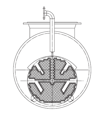
A sufficiently sized steam space is necessary for distribution of the vapour in condenser. This is granted by a bundle of pipes which are eccentrically arranged in the casing.
In the order to minimize the inlet velocity into the bundle, and thus the surface strain of the individual pipes, vapour channels are provided in the bundle increasing the inlet surface that increases the operating life and condenser efficiency.