")
")
")
|
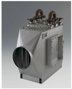
Part 1. Condensing economizer
|
|
|
|
The condensing economizer works if the temperature of the cooling water is less than or equal to 50 ° C (If the temperature is higher, then condensation of flue gases does not occur in the economizer, which greatly reduces its efficiency.) Working with gas condensate, which is a weakly acidic medium, dictates the choice of material: stainless steel AISI-316. The presence of condensate (which must not be discharged into the sewer) implies the presence of a neutralization system. If the customer wish to clean the condensate and return it to the network as the make-up water, then our company also can offer this solution.
The efficiency of the boiler system and the condensing economizer depends on temperature of the cooling water so as of the flue gases and can reach 102% (when the economizer is cooled with return heating water with a temperature not higher than 44 ° C). |
|
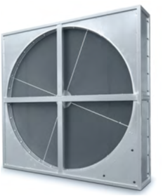
Part 2. Rotary economizer
|
|
|
|
Installation of a rotary economizer for heating combustion air taken from the street by flue gases after the condensing economizer. The casing and cladding must be made with materials that are resistant to flue gas condensation.
Installation of a rotary economizer together with a condensing one can increase the efficiency of a gas boiler up to 105% and reduce the reduction of NOx emissions to 50 mg / Nm3.
The rotary economizer cannot work if the flue gas temperature is above 70 ° C |
|
Economizer characteristics (on example of Daugavpils project):
|
|
|
|
|

The flue gas condensate economizer is designed to recover heat from flue gases, they are cooled below the dew point temperature by using the heat for the water warm up process of heating networks. The design and delivery includes a complete condensate economizer and auxiliary equipment, pre-included the following components:
- Condensate economizer.
- Condensate cooling system
- Condensate cleaning and neutralization system (maintaining pH = 6 ÷ 8).
- Flue gas bypass and dampers.
- Pumps, gate valves.
- Automatic devices and local measuring devices.
- Control system.
- Accounting for produced heat energy and used water.
- Service platforms
- Other equipment required to ensure guaranteed technical parameters.
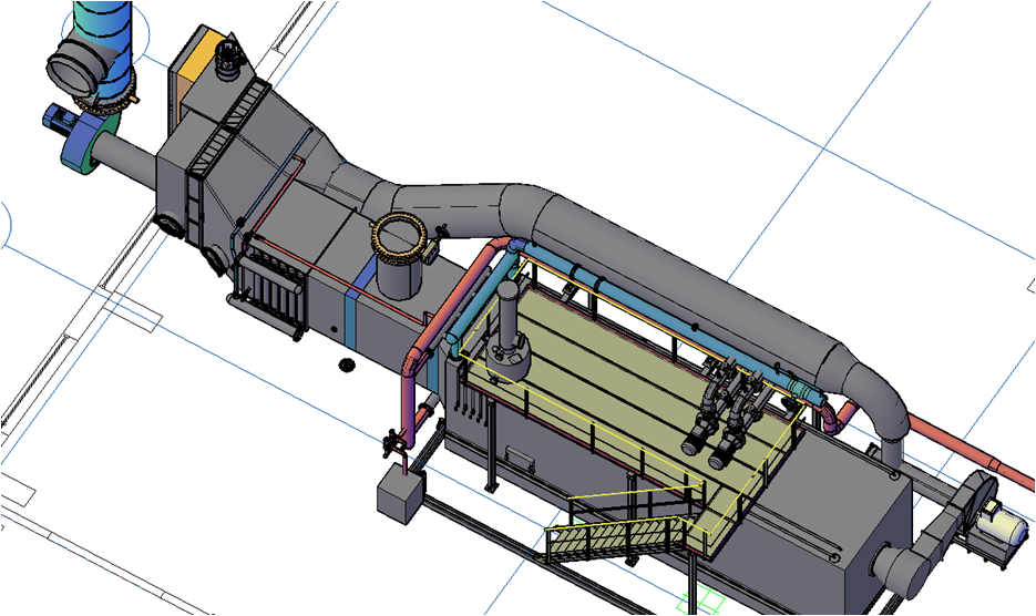
Principle:
Economizer is a vertical cylindrical unit where flue gases are strongly cooled producing thereby a contained moisture condensation. The returned heat is fed through the heat exchanger to the heating system. The flue gas economizer can also function as a chimney, in which case any additional chimney is not required.
The flue gases generated in the combustion chamber pass consistently through boiler and multi-cyclone to economizer. During maintenance period those gases use the bypass line for to get an escape pipe.
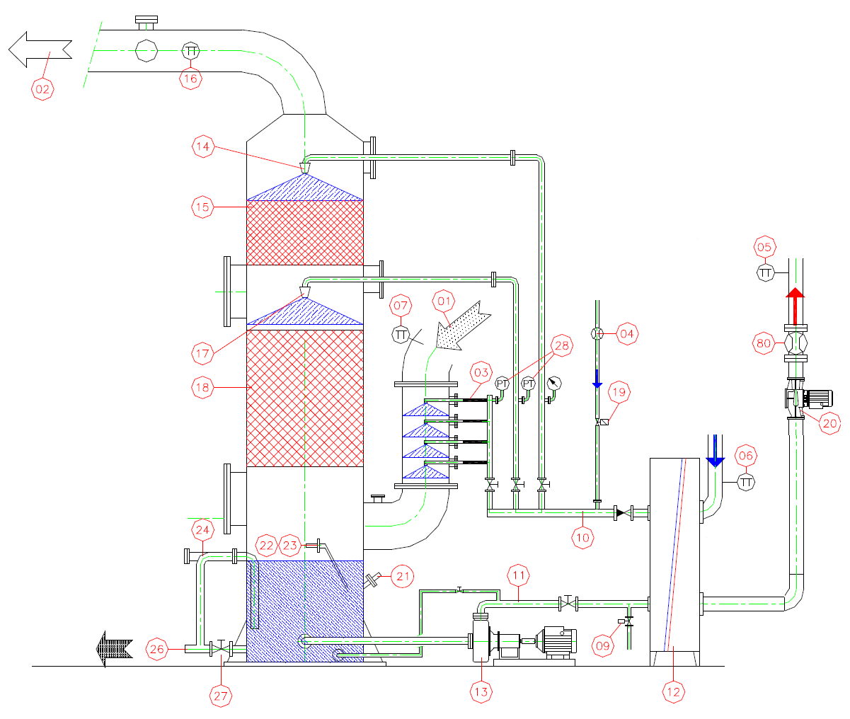
After the multi-cyclone the pre-purified flue gases comes through the flue ducts to economizer cooling pipe equipped with 4 nozzles, which cool up them.
The cooled flue gas and the spray water then passes into the scrubber tower, where the water containing the largest particles will drop into the sump. It is constantly agitated by a nozzle tube. By this, the light particles will remain floating and separated together with the surplus water.
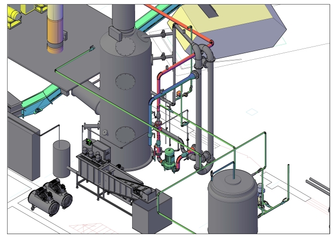
The flue gases pass subsequently through the first stuffing layer (18), which consists of tellerets (small plastic elements). It is constantly over sprayed from many small nozzles (17). In this layer, further cooling / condensing of the flue gases will take place, and the separated water will gather on the surface, assemble as larger drops which fall into the sump.
After the first stuffing layer the flue gases will pass upwards through the second stuffing layer (15), wherein the smaller droplets will assemble to a size that they fall down. It can also be said that the second layer acts as a kind of drip catcher. A central nozzle (14) is placed above stuffing layer 2 allowing constant spraying or to clean the stuffing layer, as needed.
The cooled / cleaned flue gas (02) passes out through the top and through the duct to the chimney. It is preferred that the duct slopes upward all the way to the chimney. 2 pipe branch DN 100 with flanges are placed in the duct for emission measurement.
The scrubbing tower is equipped with two inspection covers for inspection/cleaning of the sump and tellerets.
The sump in the bottom of the washing tower is equipped with overflow with water seal (24), and a drain with manual valve (27) for emptying. Furthermore, level sensors are placed in the sump (22 +23). High level will open the magnetic valve (09) on the pressure side of the pump, and a part of the water is lead out to drain or waste water treatment. Low level will ensure the addition of fresh water (19) from city water and if that does not raised the level for a predetermined time, the whole plant will be stopped.
Water for spraying is pumped from the sump. The pump (13) produces the circulation in the system.
A pH-sensor is positioned in the circuit (21) so that the pH-sensor can be cleaned during operation. Along with pH sensor a dosing pump (25) for adding of chemicals (excl.) will be delivered – to keep the pH value fairly neutral.
The spray pump injects the wash water through a heat exchanger (12) (plate or tube heat exchanger can be offered) which ensures the energy transition to the district heating water. After the plate heat exchanger the water will be split to different nozzle systems: quince, stuffing layer 1 and layer 2.
The heat exchanger is cleaned periodically, every 6000 hours of operation when the economizer system is completely stopped.
After the heat exchanger, the condensate is distributed to different economizer systems: cooling pipe, first and second layer of cavitators.
Manufacturing materials:
- Cooling tube - stainless steel
- Economizer body - fiberglass or stainless steel
- Pipes - fiberglass or plastic or stainless steel
- Condensate pump - plastic or stainless steel
- Heat exchanger - stainless steel (or other materials at the request of the customer)
Water purification (drying) system after economizer
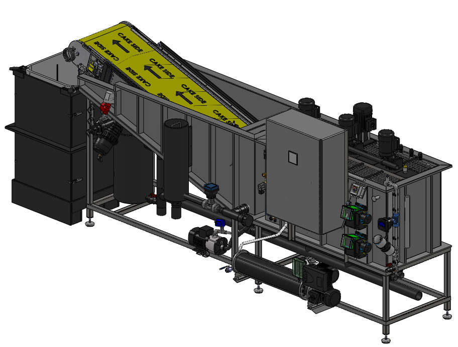
The system for removing suspended particles from condensate works according to the following principle:
When the upper sensor of the condensate level in the tank is triggered in the economizer, a valve opens, which releases part of the condensate into the cleaning equipment. Before leaving the purification system, the condensate enters the heat exchanger to pre-cool. The received heat is transferred to the room through the heater.
The condensate enters the first vessel of the equipment, where the pH value is adjusted to 6.0-7.5. Then the condensate flows into a container, where a special chemical reagent is supplied - a precipitant, which precipitates unburned particles. Then the condensate is fed into the third tank, into which the particles are connected and combined with the help of the polymer. Mixers are installed in all three tanks, which constantly maintain a homogeneous environment. From the last container, the water with the combined particles enters the belt filter. The material of the belt allows water to pass through, and the dirt is trapped by the belt filter and enters the collection bag. After cleaning, the neutralized and transparent condensate is drained into the drain.
SECTIONS
Contacts
Veteranu str. 5-А,
VISAGINAS LT-31114
Utena cap.
Lithuania LTU
+(370) 386 71 481
Quick SMS
Contact us
Your message has been sent sucessfully