TECHNICAL DATA
Boilers for electricity production (co-generation)
- Thermal capacity – from 9 MW up to 75 MW
- Max. working pressure – 58 bar
- Temperature – up to 450 С
Boilers for process steam production
- Thermal capacity – from 7 MW up to 70 MW
- Max. working pressure – 22 bar
- Temperature – up to 200 С
Hot water boilers
- Thermal capacity – from 3 MW up to 10 MW
- Max. working pressure – 14 bar
Advantages:
- Furnace design specifically for firing biomass fuels. Not a redesign of a fossil-fuel fired furnace.
- Better combustion, lower emissions, ability to burn wetter fuels successfully.
- Lower carry-over of particulate matter due to better furnace control.
- Boilers meet or exceed the requirements for emissions of particulate, SO2, NOx, and CO as stipulated by Lithuanian and Latvian authorities.
- Boilers have generous volume, which means that moisture-laden gases pass through the boiler more slowly, reducing erosion.
- Proprietary designs, superior manufacturing capabilities, and a full engineering staff give us flexibility to take on many types of projects.
- Over 300 successful energy system projects, worldwide.
Sohrt description:
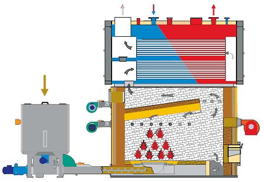
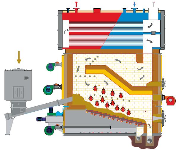
- The portion of the boiler which sits directly above the furnace cells constitutes the radiant section of the boiler. Combustion of the volatile gasses produced by the furnace cells is completed in this zone, radiating energy to the boiler waterwalls, roof section, screen tubes, and superheater section, what allows to burn wood fuel with high moisture content (50-62%)
- Combustion air is introduced into the furnace cell in three separately controlled zones; undergrate air, overfire air, and tertiary air. The undergrate air is introduced through the grates through linear controlled dampers at low pressure. The overfire and tertiary air is independently controlled with linear dampers, and is first directed around the outer periphery of the cell where it absorbs heat from the refractory while simultaneously cooling the cell, then through multiple tuyere holes. The tuyere holes are formed tangentially in the cell refractory, creating a cyclonic action. The undergrate air is used for gasification of the wood-fuels. The volatile gasses are then ignited in the zone directly above the fuel pile, and combustion is completed in the upper portion of the furnace cell and the boiler water-wall combustion chamber. This staged combustion process and the manner in which the air is introduced into the furnace cell contributes to low carry-over and reduced emissions, increase boiler efficiency.
- The boiler system is controlled with a computerized control system developed and serviced by software engineers. The superheater temperature is controlled with an attemperation coil in the mud-drum, through which a portion of the steam is diverted to maintain precise temperature at the outlet of the superheater. The system is based on a Hewlett-Packard computer, with accompanying peripherals and proprietary software. Computerized control systems are simple to operate and maintain, are password protected, and have excellent historical data storage and retrieval.
- Fuel supply to the furnace system is designed in such way that air inlow from transportation system to the furnace is almost oimpossible - all feeding and transmisssion scerews are in closed jackets. Clearances between jackets and screws caculated in such way, that it would be always filled with the fuel during boiler operation.
- High fuel combustion efficiency and installation of reliable flue gases cleaning equipment secure low emissions level.
- The water-cooled rotary grate system is comprised of pairs of water-cooled rotating tubes with intermeshing teeth welded to the outer periphery of each roll. The rolls index in a ratcheting manner creating a grinding effect on the ash. The teeth are spaced at intervals allowing for the knobbed surfaces to pass by each other and to also provide space for passage of undergrate combustion air. The hydraulically operated rolls are assembled in pairs, tied together to rotate in opposite directions. At timed intervals, each pair of rolls rotate, crushing the ash between them, and dropping it to a conveyor below. Should an overload condition occur, the pair of tubes suffering the overload may be reversed.
- High quality and reliability of boler system, it’s maitenance and repair costs are very small.
- It is possible to supply separately boiler or full boiler system completed with all reuired equipment and accessories, also with steam turbine for electricity generation.
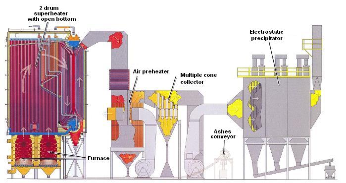
Diagram of a steam boiler for biomass combustion
JSC “GANDRAS ENERGOEFEKTAS” offers boilers for different kind of pellets (pellet boilers) and wood logs burning.
TECHNICAL DATA
Thermal capacity
- automatic boilers: 14 kW - 1163 kW
- manual boilers: 29 kW - 930 kW
Fuel type
- for automatic boilers: wood pellets, agropellets agropellets (for example, cotton waste) , straw pellets , sun flower husk pellets, peat pellets (max. humidity up 25 %).
- for manual boilers: wood logs and wood pieces.
These boilers can be used for production of how water with max. temperature 110 C and max. working pressure 6 bar.
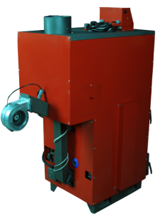
Manual fuel supply boilers
|
|
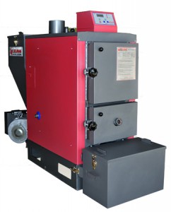
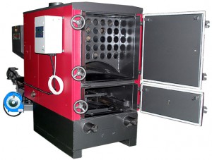
Automatic fuel supply boilers 14-290 kW
|
|
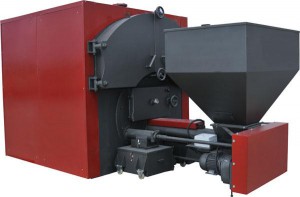
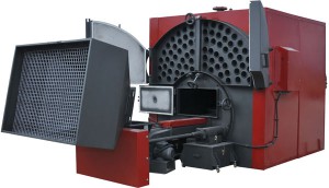
Automatic fuel supply boilers
348-1163 kW
|
|
|
|
|
|
 |
|
 |
|
 |
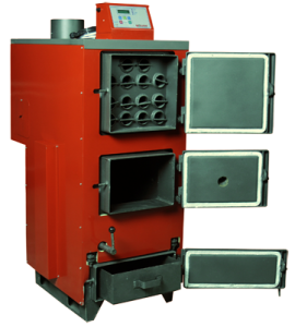
SHORT DESCRIPTION:
Monoblock design boilers made of steel with smoke tubes have special turbulence promoters to increase boiler operation performance.
Boiler has two separate doors for tube part and combustion chamber inspection.
Fuel supply to the boiler can be in automatic mode or manually.
In case of automatic fuel supply boiler will be supplied with receiving bin, which has fuel level switches, ensuring fuel supply system switching on (in case of fully automatic boiler plant operation) or gives signal to the personal about low fuel level. There is also minimum fuel level switch, achieving which boiler’s automatic system stops it.
It is possible to supply automatic ignition system.
It is possible to supply modulation system, which will keep automatically adjusted outlet water temperature in the same time adjusting quantity of supplied to the boiler fuel and combustion air.
In case of automatic fuel supply, ashes, which appear in the combustion chamber, are removing automatically by means of two screw conveyors to the ashes collecting containers.
Boilers are manufactured in accordance with International standard TÜV CERT and have CE marking.
Warrantee time for these boilers is 2 years.
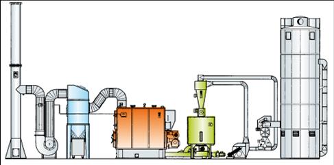
We are ready to offer You complete boiler plant on turn-key basis with all required equipment:
- Vertical or horizontal silos for fuel storage,
- Moving floors,
- Vertical or horizontal fuel supply to the boiler transporters,
- Boilers with automatic fuel supply and ash removing system,
- Automatic smoke tubes surfaces cleaning system,
- Economizer,
- Multicyclon (smoke filter),
- Chimney,
- Automatic control system (PLC),
- Remote monitoring system
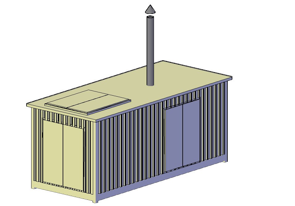
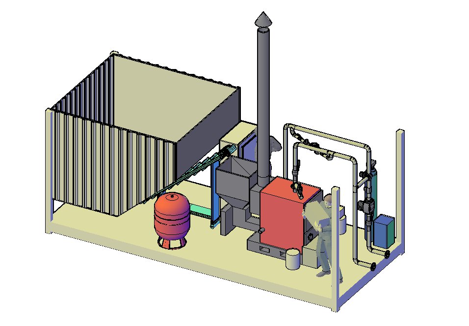
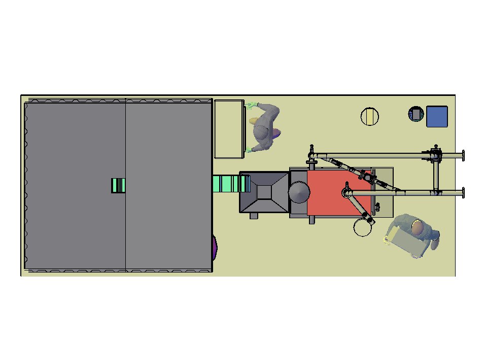
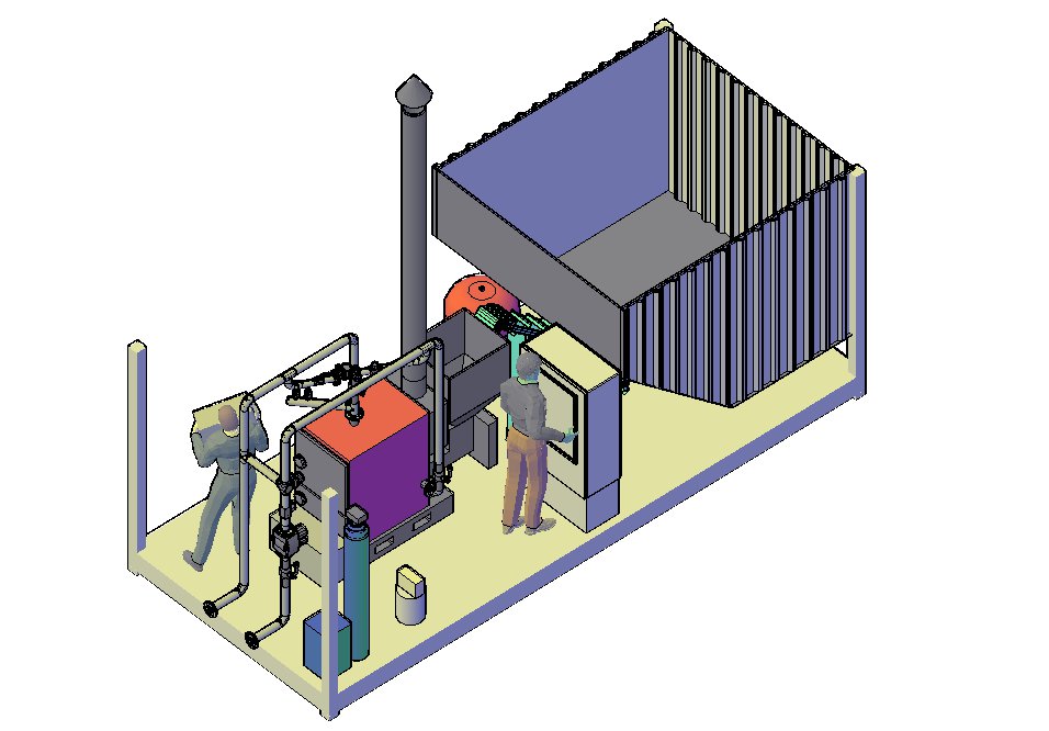
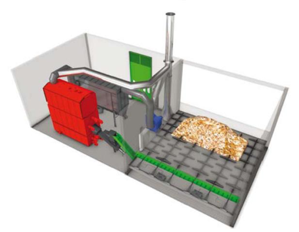
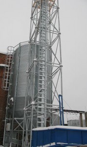
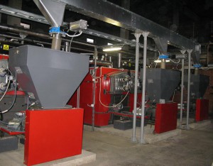
Fully automatic boiler plant example
Local boiler plant Kalkuni, Daugavpils, Latvia - 3 boiler with 400 kW heating capacity each.
Fuel receiving bunker, vertical fuel loading to the storage silo elevator, 80 m3 capacity storage silo.
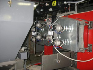
Boilers with receiving bins and fuel supply transporter
Automatic smoke tubes surfaces cleaning system
")
")
")